As I’ve researched the history of Cumbernauld, and in particular the area around the Station, I realised how many of my forebears were involved in the life of that area. A number were involved in the brick works and the railway, not to mention owning a shop and running a bus hire firm. The railway still operates but most of the buildings, except Station Buildings, have gone. It got me thinking that it would be fascinating to see if I could recreate a model of the Station and its immediate surroundings. My research uncovered a number of images featuring the Fireclay Works and included details of the immediate area and the layout of the railway line.
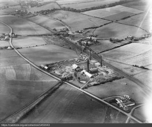
This provided the inspiration to plan a model railway layout. It took a long time cross-referencing images to determine the real-life layout. It was an extremely industrious area – the Fireclay Works, a Granary, numerous small business, and of course the railway itself.
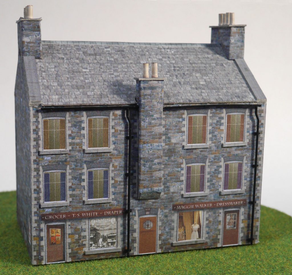
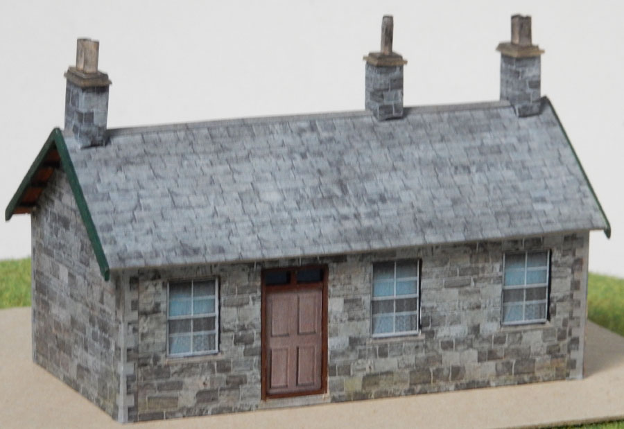
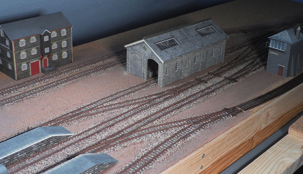
Having established a basis for the track layout, there was a realisation that any buildings would need to be scratch-built as there was nothing for this era that would be available off-the-shelf. Unless a new skill could be learned, there was little point in going further. So began the process of experimenting with card kits in order to understand how they were made. Eventually it became possible to create building sections in a computer graphics package with textured walls and roofs. These were printed out on A4 sticky labels and affixed to 1mm card. See below for the first buildings that were produced.
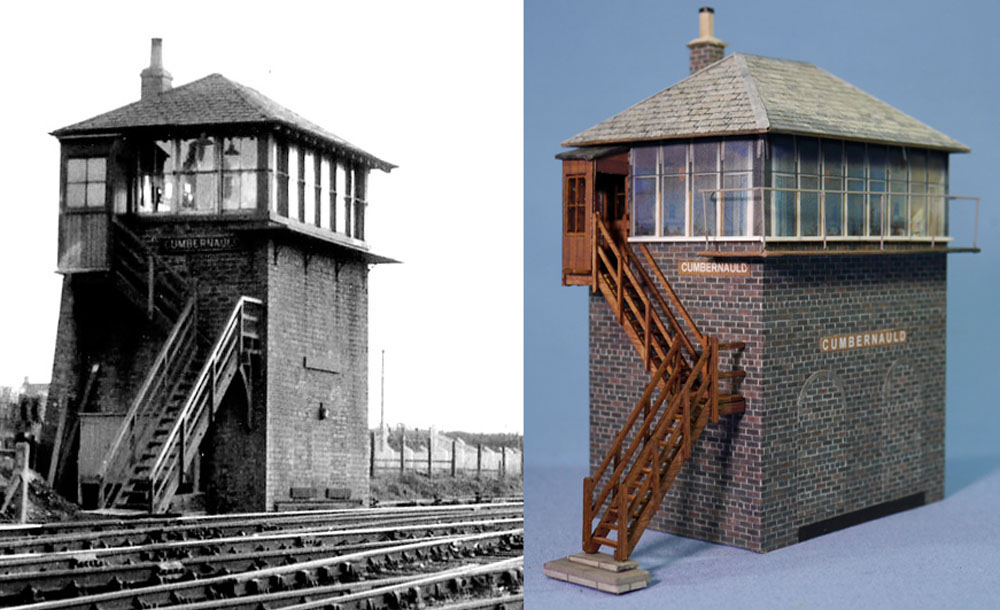
Work on the layout has progressed but I’ve failed to update the page until now (10th June 2020). One of the major challenges was to see if I could create a model of the signal box. After much trial and error I think I now have something that looks credible. The windows were taken from a photo of the Caledonian signal box at Bo’ness. I’ve made it in dark brick although when built it would have been a pristine red brick.
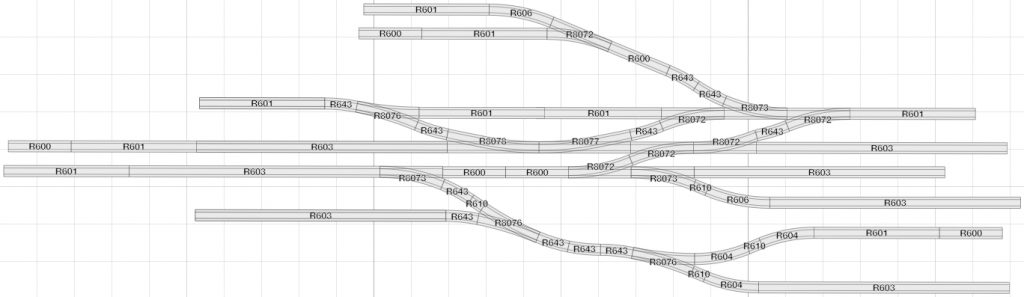
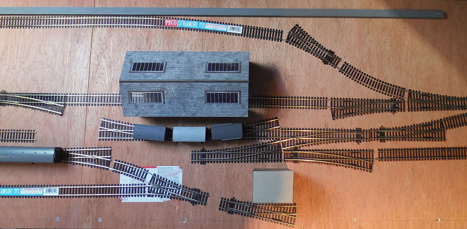
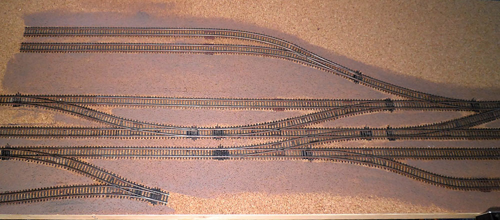
Having the confidence now to create the buildings, it looked as if it would be safe to progress to the layout itself. Working from the plan, I began to layout the track on the board (9mm ply later covered with 3mm cork).
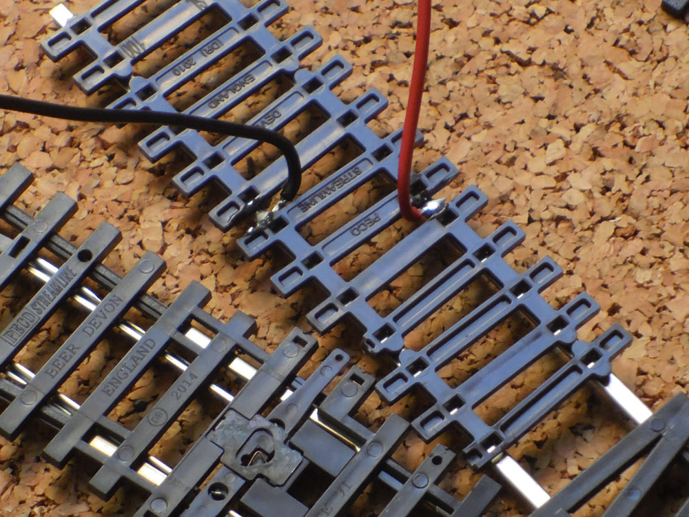
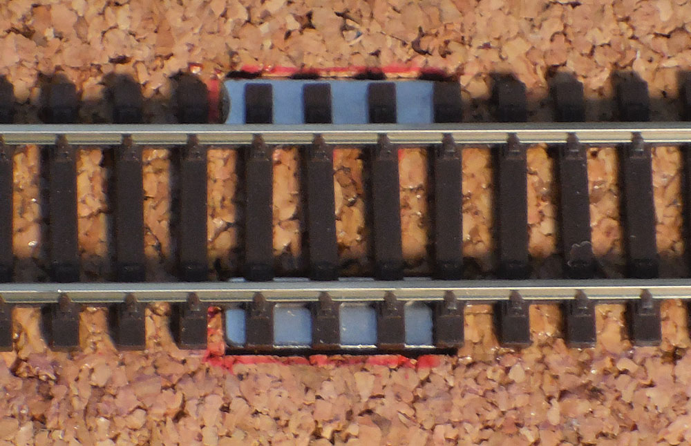
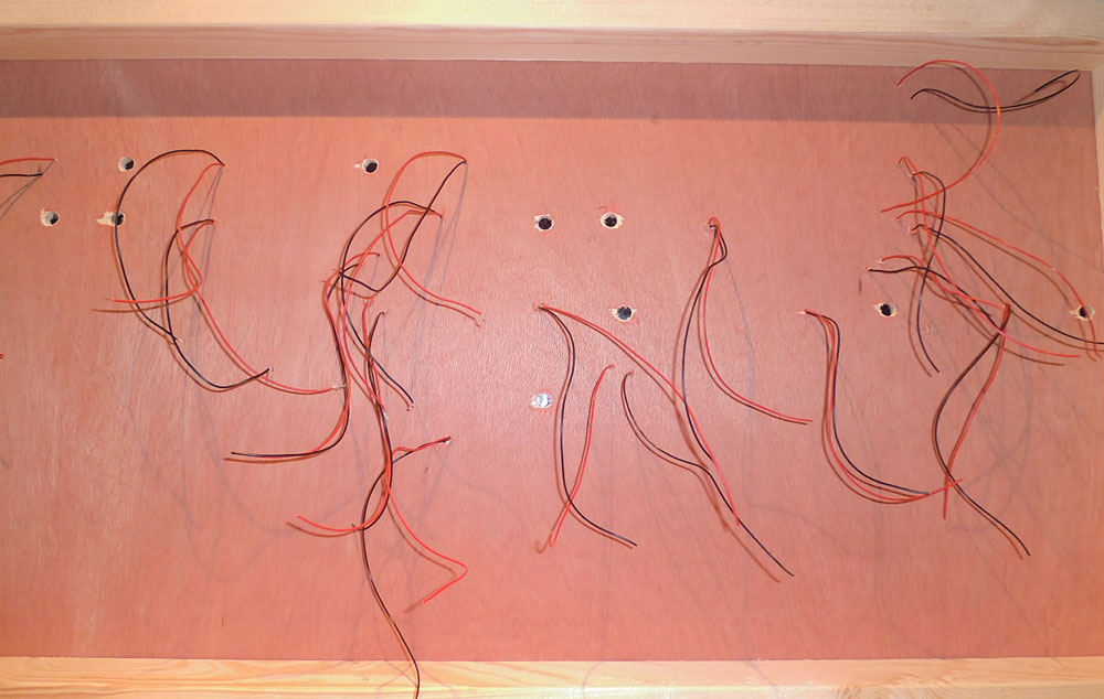
The next big step was to fix down the track. After much deliberation I decided, as a newcomer, to go for Insulfrog points. Electrofrog would be better but it would commit me to the use of solenoid motors and additional wiring that I wished to avoid at this stage. While many people rely on the rail joiners, the general advice is to hard wire each piece of track with droppers for extra reliability. I also decided to plan for the later addition of solenoids for the points, so holes were drilled in the baseboard to accommodate these. In addition, I planned to allow for the use of Kaydee couplings to enable more efficient coupling and uncoupling of wagons. I developed a method of doing this using Neodymium magnets.
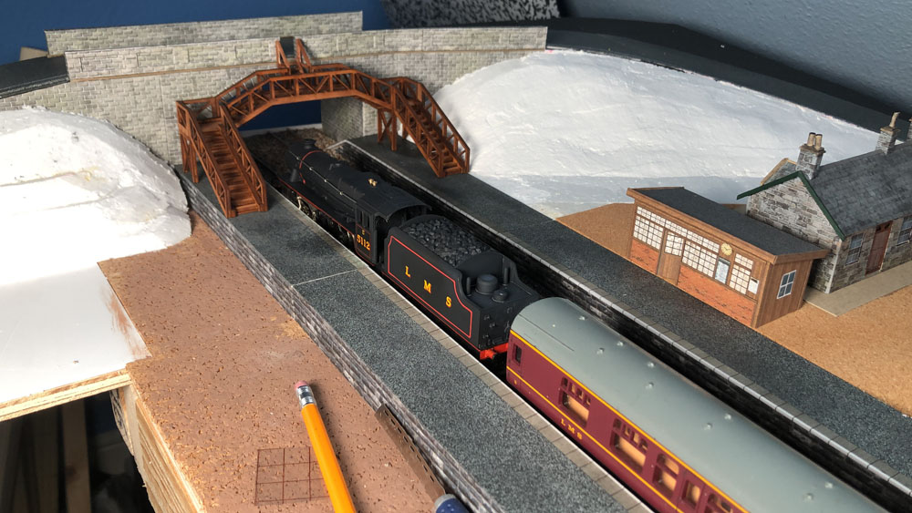
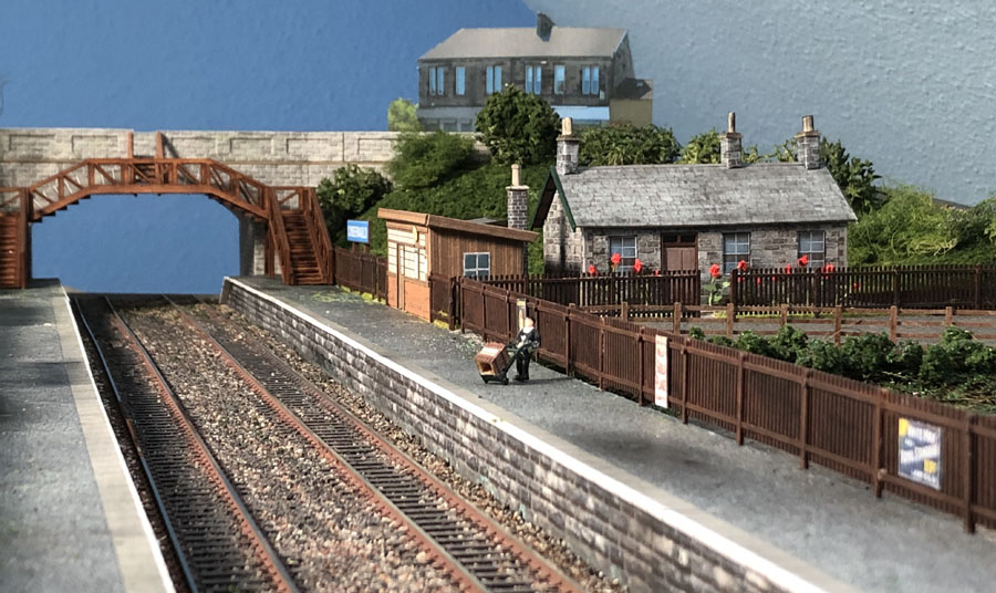
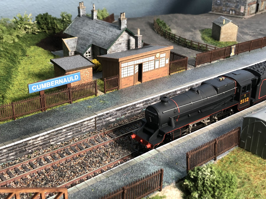
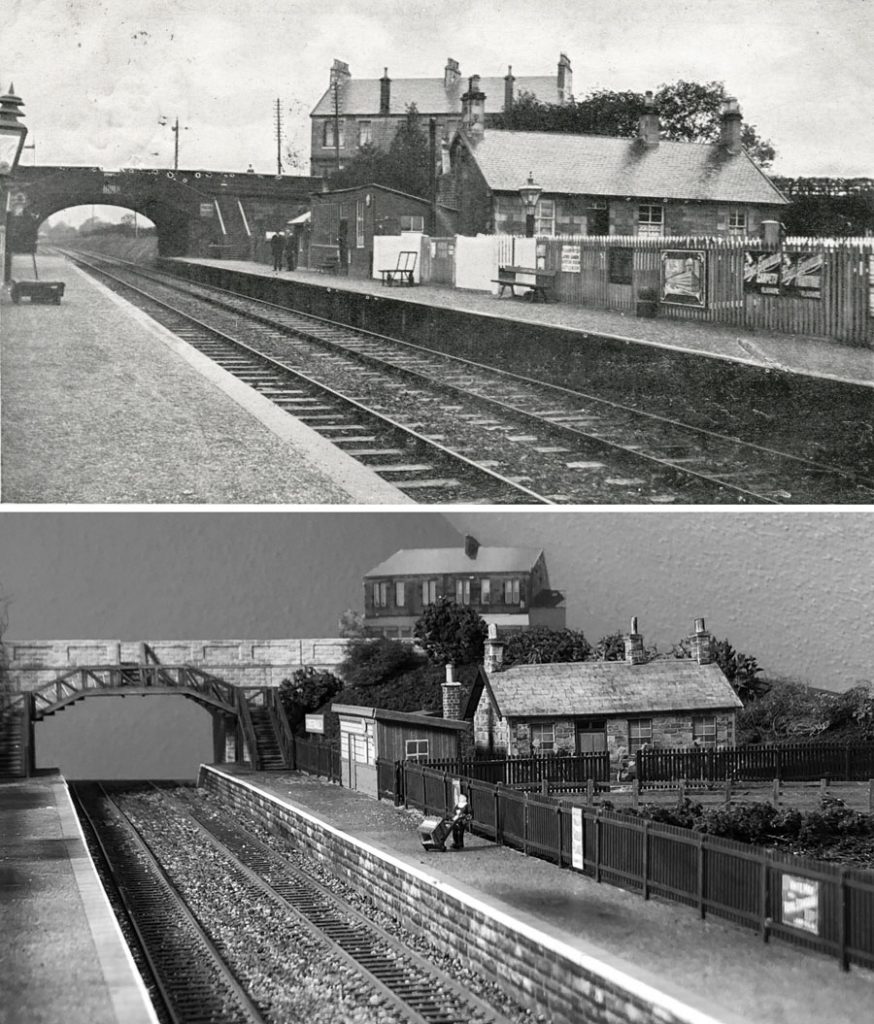
It wasn’t easy to find a bridge that would look correct but I was able to modify a Metcalfe kit so that it wouldn’t look out of place. Work also progressed on the ticket office. Many of us remember the converted railway coach that served as a waiting room on the other side, but when built, and up to 1930 at least, both waiting rooms were the same.
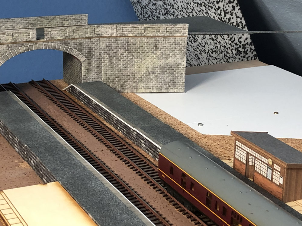

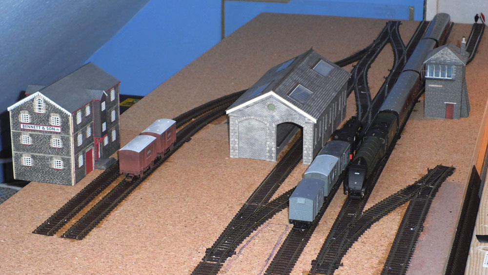
As mentioned above I decided to a cover the whole baseboard with 3mm cork. Many people only place cork under the track, but I quickly realised that if you raise the track, then you also have to raise platforms and buildings. Looking at old photos there isn’t a great ballast shoulder on the track so I decided I would just add ballast rather than raise it. See the ballasted track below with a few buildings and the platform in place. The rail sides were also painted with a rust effect paint.
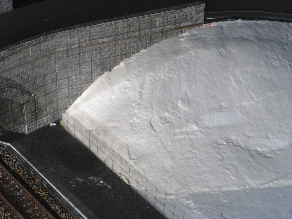
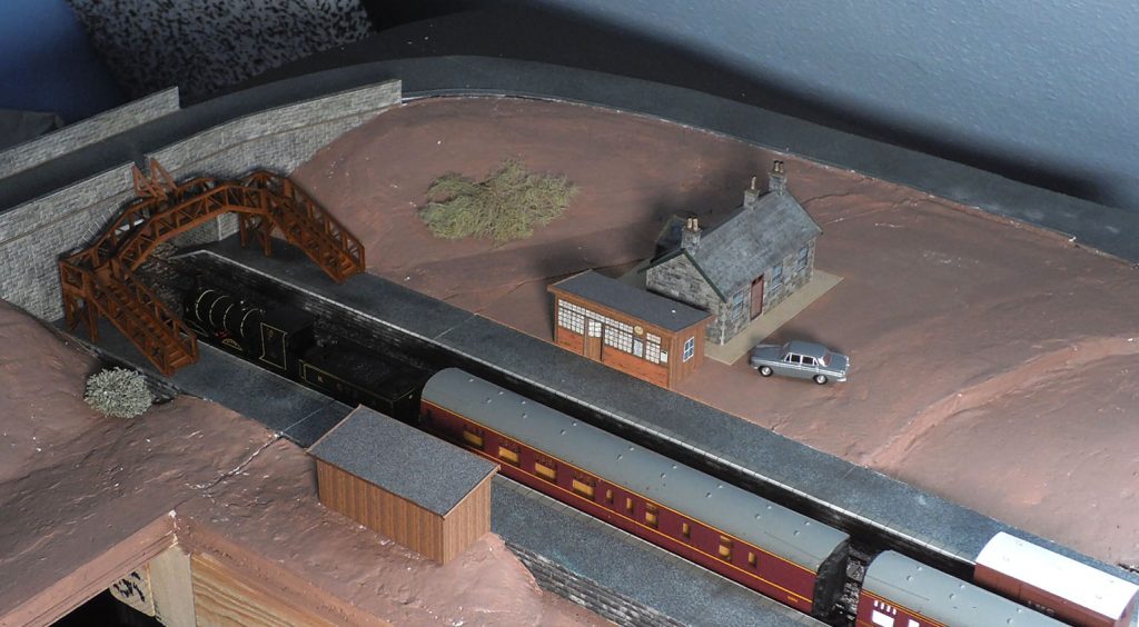
The bridge did actually cross the line at an angle but I took the easy option and crossed the line at right angles. The next step was to build up the banks and raise the ground level for the cottage and ticket office. This was done by shaping polystyrene which was then covered with Sculptamold (plaster).